
Honda B-Series Turbo Heat Management: EG, EK & DC2
Posted by Matthew Marks on 16th Jul 2026
Jump to a section
Honda B-Series Turbo Heat Management: EG, EK and DC2 Guide
A turbo B16, B18 or B20 usually puts the manifold and turbo at the front of the bay near the grille. This guide helps you protect the front hot-side area, nearby brake lines, wiring, hoses, intake pipework, bonnet underside and radiator-side components before buying a blanket, wrap, sleeve or shield.
On an EG, EK or DC2, the manifold position and pipe routing matter more than the chassis when choosing heat protection.
The simple answer
Start with the turbine housing, manifold, downpipe and external wastegate if fitted. Then identify the part at risk: wiring, hoses, fuel or brake lines, intake pipework, radiator/fan parts, bonnet underside or painted panels in the front hot-side area.
Fix leaks, damaged insulation and unsafe routing first. A correctly sized turbo blanket can control heat at a compatible turbine housing; exhaust wrap suits suitable manifold or downpipe sections; heat sleeve protects safely routed lines and looms; and a rigid shield or reflective material suits an exposed panel or surface.
Do not choose a product from “EG”, “EK” or “DC2” alone. Turbo size, manifold position, wastegate routing, engine movement, and clearance determine the right answer.
- Plan the hot side before final assembly, not after a hose or loom has been damaged.
- Measure the turbine housing before choosing a T25, T3 or T4 turbo blanket.
- Treat an external wastegate and its outlet pipe as separate heat sources.
- Reroute and secure lines before adding the heat sleeve.
- Use a shield or reflective material on a suitable surface, not directly on turbo or exhaust parts.
Why EG, EK and DC2 turbo builds need a heat plan
Honda B-Series bays are compact, and a turbo conversion changes the space around the front exhaust side of the engine. A top-mount, ramhorn or low-mount manifold can put the turbo, wastegate and downpipe in different front-of-bay positions.
The nearest vulnerable part may be a brake line, fuel line, loom, radiator hose, fan, intake pipe, A/C line, bonnet underside or painted panel.
That is why the useful order is always the same: identify the heat source, identify the vulnerable part, check clearance and routing, control heat at source where practical, then protect what cannot be moved. A blanket or sleeve is not a substitute for fixing an oil leak, a loose exhaust, cracked insulation or a line touching hot pipework.
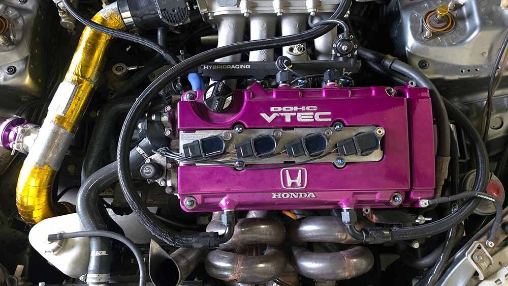
Plan heat protection around the actual manifold, turbo and line routing, not the chassis code.
For the wider parts list, boost-control choices and conversion planning, use our Honda Civic B-Series and K-Series turbo guide. This page focuses on the heat-management decisions that follow once the hot-side layout is known.
How heat reaches parts around a turbo B-Series
The important type of heat here is usually radiant heat: heat travelling directly from a hot turbo, manifold, downpipe or wastegate to the part in its line of sight.
On the Civic layouts shown here, that normally means front-of-bay parts such as looms, hoses, brake-line routes, radiator/fan components, intake pipework, the bonnet underside and nearby painted panels.
Conducted heat travels through contact. A line clipped to a hot bracket, a loom touching a downpipe, or a shield bolted directly against a hot pipe can transfer heat into the vulnerable part.
Convected heat is hot air moving through the engine bay; it becomes more noticeable after repeated pulls, stop-start traffic, dyno sessions and track use as the bay heat-soaks.
The fix depends on the path. A turbo blanket or exhaust wrap targets a hot source.
A rigid shield creates a physical barrier. Reflective material is for a suitable nearby surface facing the source. A sleeve is for a hose, line or loom that is already routed with real clearance. Treating every problem with the same product is how an otherwise tidy build ends up with hidden contact points.
Before you order: the B-Series hot-side checklist
Do this check with the car fully cold. The goal is to leave with dimensions, photographs and a clear list of risks—not just an impression that the bay “looks hot”. If the engine is still being mocked up, repeat the check once the final manifold, turbo, downpipe, intake and engine mounts are installed.
- Turbine housing: measure the hot-side circumference and width; photograph the actuator, compressor cover and anything that could foul a blanket.
- Wastegate: record the make/model or stated size, then photograph the body and outlet route separately.
- Exhaust route: trace the manifold, downpipe and outlet pipe from the turbo to the floor. Mark sensors, V-bands, flex sections, clamps and service points that must stay accessible.
- Vulnerable components: identify oil and coolant lines, fuel and brake lines, vacuum hose, boost-control hose, wiring, connectors, intake pipework, reservoirs and panels in the line of heat.
- Movement: allow for engine rock on the fitted mounts. A cold clearance that disappears under load is not a safe clearance.
- Condition: find oil residue, coolant staining, fuel smell, chafing, brittle insulation, loose clips and contact marks before adding any protection.
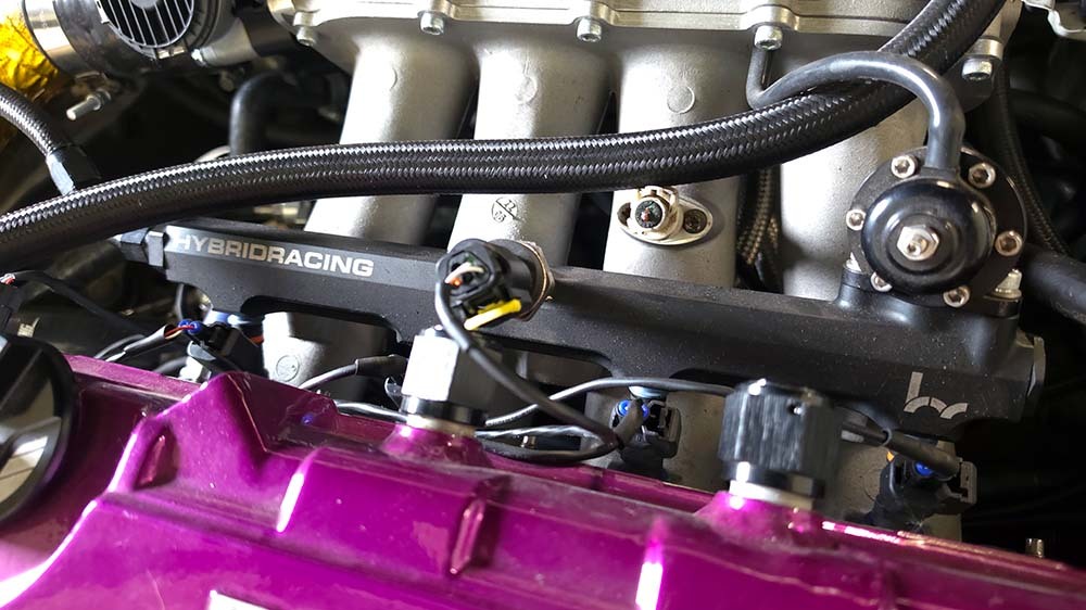
Include nearby fuel, vacuum and wiring routes when checking the hot side.
Choose the first heat-management move for the problem
A compatible turbo blanket may control radiant heat at the turbine housing, but it must not foul the actuator, linkage or surrounding pipework.
Exhaust wrap can suit appropriate pipework; it should not hide a leak, damaged section, sensor, joint or clamp that still needs access.
A heat sleeve is supplementary protection for a route that stays clear through engine movement; it does not make direct contact with exhaust parts acceptable.
A rigid shield with an air gap or reflective material on a suitable clean surface can reduce radiant exposure; it is not exhaust wrap.
Control the heat at the turbocharger and wastegate
On a B-Series turbo build, the turbine housing is often the best place to start because it is a concentrated source of radiant heat.
A blanket only works as intended when it fits the turbine housing correctly and leaves clearance around actuator arms, wastegate linkages, compressor housings and anything that moves.
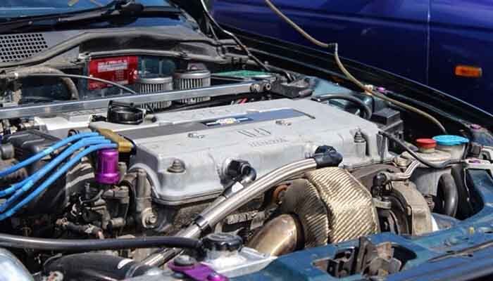
A turbo blanket helps only when the housing size, fit and surrounding clearance are right.
Measure the turbine housing rather than relying on the turbo flange name or the vehicle. Our turbo blanket size guide explains the T25, T3 and T4 starting points. If an external wastegate is fitted, identify its stated size and inspect the outlet route as well: the blanket covers the wastegate body, not the screamer pipe.
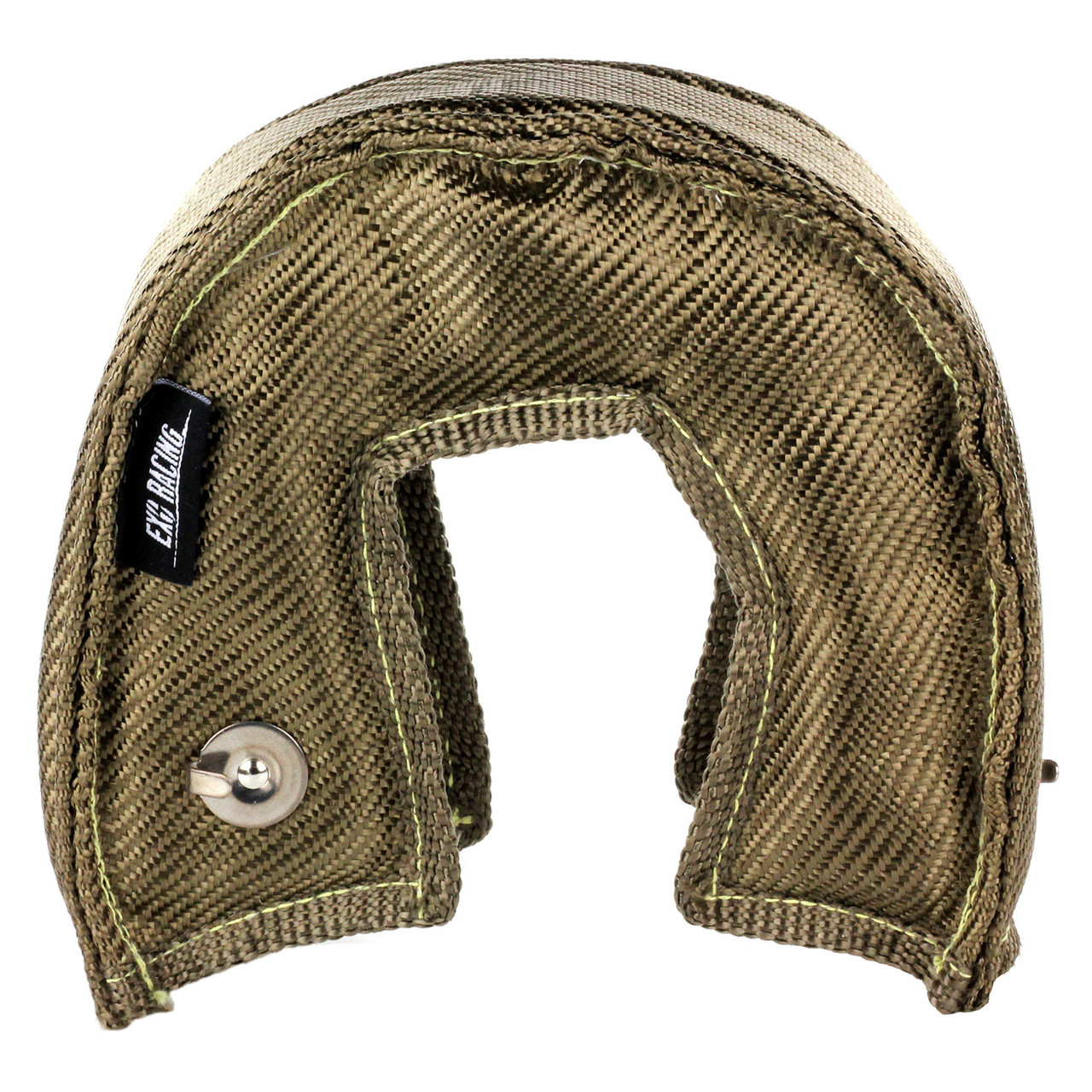 Exoracing Turbo Blanket V3
For a correctly measured turbine housing, where controlling turbo radiant heat is the main job.
From £119.99
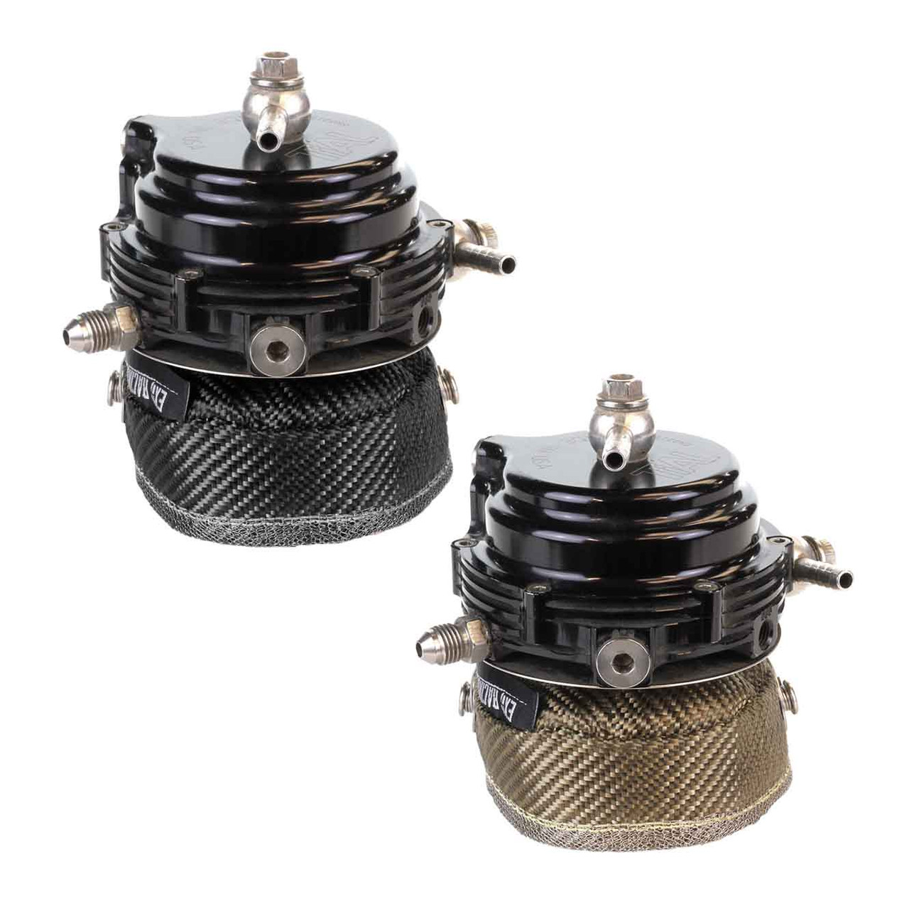 Exoracing External Wastegate Blanket Titanium or Carbon
Match this to the stated external wastegate size after confirming a safe outlet-pipe route.
From £64.99
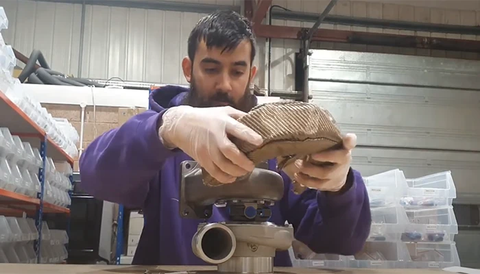
The blanket belongs on the turbine housing, not the compressor side. Our turbo blanket installation guide shows the fit and spring checks in more detail.
Watch: Turbo blanket fitting and first heat-cycle checks.
If you cannot see the video above, watch the turbo blanket installation video on YouTube.
Manage manifold, downpipe and line exposure
The manifold, downpipe and wastegate outlet can still radiate heat after a turbo blanket is fitted.
Exhaust wrap is suitable for exhaust pipework, not for wiring, rubber hose, sensors, flex sections, leaking joints or serviceable connections. Decide whether the pipe can be safely wrapped before covering it.
Oil feeds, returns, coolant lines, vacuum lines and looms should be routed and supported so they cannot touch hot exhaust parts when the engine moves. Once the route is safe, a heat sleeve can provide an additional layer around the exposed section. Measure the outside diameter before selecting a sleeve; use our heat-sleeve size chart if you need help choosing a diameter.
Watch: Silicone fibreglass heat sleeve installation.
If you cannot see the video above, watch the silicone heat-sleeve installation video on YouTube.
Oil feed, return and coolant lines
Do not concentrate only on the line nearest the turbo. Follow the full route from fitting to fitting, including where it passes brackets, clips, the radiator side and the front hot-side area.
An oil or coolant line should not be rubbing on a manifold, a downpipe, a sharp bracket or a moving component. Fix weeping fittings and worn hose before fitting a sleeve; protection cannot make a leaking line safe.
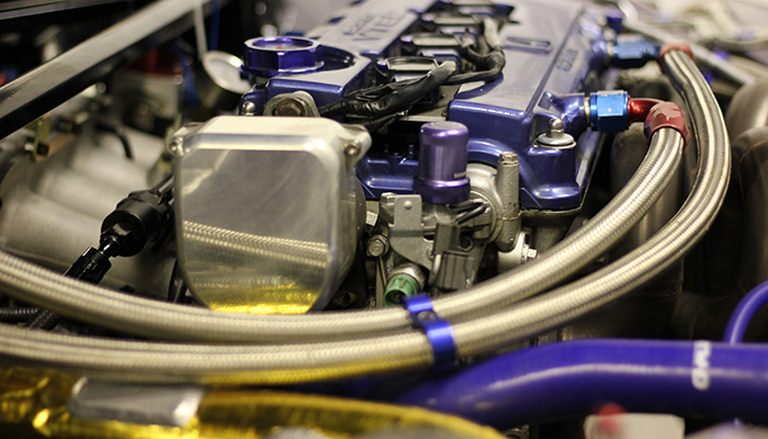
Check hose and fitting condition before sleeving; protection should not hide a poor line assembly.
Vacuum hose, boost-control hose and wiring
Keep boost-control and vacuum hose away from both the wastegate body and its outlet pipe.
Use clips or supports that leave enough slack for engine movement but do not permit the hose to sag onto the hot side.
For wiring, inspect the insulation and connector body first. A sleeve is useful as additional protection around a sound loom; it should not conceal brittle insulation, exposed copper or a damaged connector.
Fuel and brake-system components
Treat fuel and brake-system exposure as a reason to stop and reassess the layout, not as a reason to add the nearest product.
Confirm the route, fittings, retention and clearance first. If a hot pipe is close to a fuel or brake component and you are unsure how to create a safe separation, get vehicle-specific professional advice before hard use.
 Exoracing Titanium or Carbon Exhaust Wrap
For suitable manifold, downpipe or hot-side pipework that needs less radiant heat in the bay.
From £24.99
 Exoracing Silicone Fibreglass High Temperature Heat Sleeve 0.5m
Supplementary protection for correctly routed hoses, lines and wiring near the hot side.
From £14.99
Front brake line, bonnet and intake-side protection
On a normal B-Series EG, EK or DC2 layout, the turbo manifold is at the front of the car near the grille, not beside the bulkhead.
Focus this check on the front brake-line route, radiator/fan area, intake pipework, A/C hard lines, bonnet underside and painted panels that face the hot side.
Only treat bulkhead heat as a relevant risk on an unusual custom layout where the exhaust side genuinely faces it. Improve clearance first, then use a rigid shield with an air gap where the layout allows, or apply reflective material to a suitable clean surface. Do not stick reflective material directly to a turbocharger, manifold or downpipe.
Our own B-Series AWD Civic build is a useful reminder that final exhaust routing can change the plan for nearby components: its route required attention to the location of the chassis brake lines. Mock up the manifold, turbo, wastegate and downpipe before committing to final line clips, shielding and reflective protection.
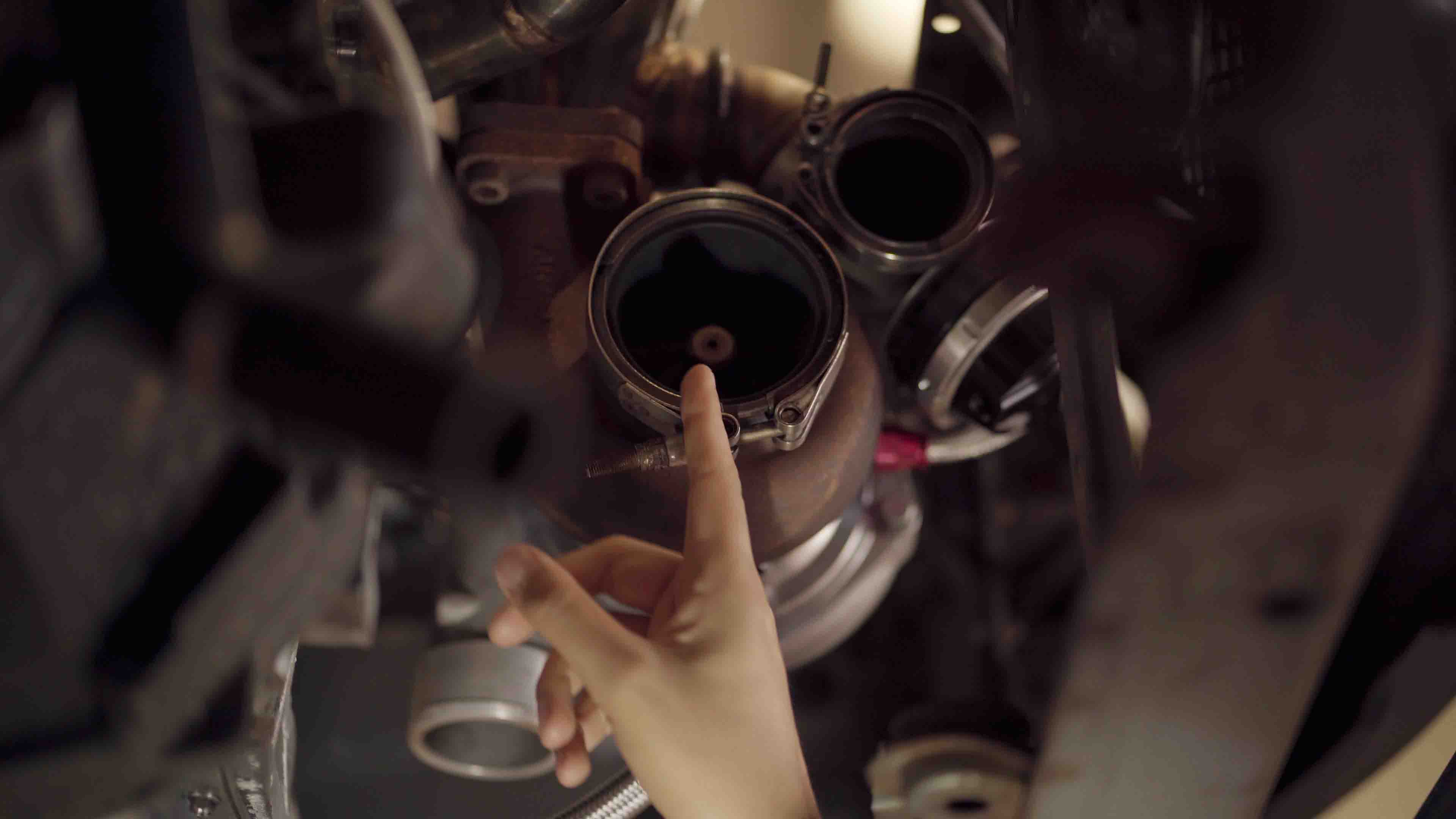
For a fuller explanation of where reflective material belongs, see our heat-reflective tape guide.
EG, EK and DC2 build scenarios
The following are planning examples, not fixed packages. They are deliberately based on the hot-side layout and use case rather than a promise that any part fits every EG, EK or DC2.
Road car with an internal wastegate
Begin with the turbine housing and the nearest vulnerable hose or loom. If the turbo is compatible, source control at the turbine housing may be the first useful product. Then assess the downpipe and any line that passes through the front hot-side area. A full wrap-and-shield stack is not automatically necessary if routing and clearance are already good.
External-wastegate fast-road build
Plan the wastegate body and the outlet pipe independently. The body may need a correctly sized wastegate blanket, while the outlet route may need repositioning, suitable exhaust wrap or shielding to keep it away from lines and panels.
Check the vacuum reference hose and solenoid wiring after the first heat cycle because these are easy to overlook during a mock-up.
Track, drag or repeated hard-use build
Repeated high-load use gives heat soak more time to build. Plan source control at the turbo and appropriate exhaust pipework, secure line and loom protection, and a robust barrier where the bonnet underside, front panel or intake-side surface remains exposed.
Build inspection into the routine: a system that is safe after a short road run may show movement or contact after longer, harder use.
Cold inspection versus first heat-cycle inspection
Confirm housing and wastegate dimensions, leaks, routing, service access, line condition and the gap between the hot side and each vulnerable component.
With the system cool, look for moved blankets, loose springs or ties, lifted reflective material, fresh staining, contact marks, hose hardening and a loom or line that has settled toward heat.
When a heat product is not the first fix
Likewise, do not fit a turbo blanket over contamination, use a heat sleeve to hide a damaged hose, or wrap a component simply because it looks close in a photo.
The hot side must stay clear through vibration and engine movement. If access or routing is uncertain, use a competent Honda/turbo specialist before driving the car hard.
Common B-Series turbo heat-management mistakes
- Buying by chassis name alone. Measure the turbo and wastegate, then check clearance on the actual car.
- Protecting a line before correcting its route. Secure it away from the hot side before adding a sleeve.
- Ignoring the screamer pipe. It is a separate source of heat and must not be aimed at a loom, hose, brake component, radiator/fan part or painted surface.
- Fitting over a leak. Clean and repair the area before fitting any blanket or wrap.
- Forgetting the first heat-cycle check. Let the car cool fully, then inspect for movement, loose fasteners, contact marks and fresh damage.
Pre-drive heat-cycle check
After fitting a blanket, wrap, sleeve or shield, allow the vehicle to complete a gentle heat cycle in a suitable ventilated area, then let it cool fully before inspecting it. Check that blankets and springs remain secure, wrap is tight, shields are fixed, and no hose, line or loom has settled closer to the hot side.
For exhaust-wrap overlap, securing and first-cycle smoke guidance, follow our exhaust wrap installation guide. Stop and investigate rather than continuing to drive if you find a fresh leak, electrical damage, exhaust contact or a brake-system concern.
What our 500whp turbo AWD EK taught us about B-Series heat
Our own 500whp turbo AWD Honda Civic EK has been a useful B-Series reference because it makes the usual heat problems impossible to ignore. On this sort of layout, the breather lines from the rocker cover can sit above the manifold and very close to the hot side. They look simple during mock-up, but that proximity can become a long-term heat-management problem if the manifold and lines are treated separately.
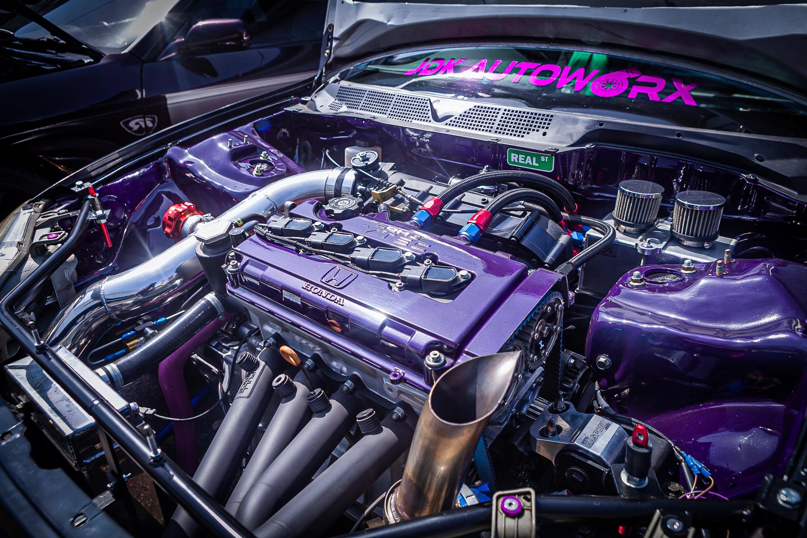
Real-world Jdkautoworx AWD EK makes the manifold, breather line, oil line and wiring checks much easier to understand.
Our practical approach is to reduce the radiant heat coming from the manifold with suitable exhaust wrap, then protect the breather lines with a heat sleeve once their route is safe and properly supported.
We would not rely on the sleeve alone where a breather line remains extremely close to the runners: it may protect the outside of the line, but it does not remove the source of heat or create clearance.
The same applies to a block breather route: check the whole line, not just the fitting. It can start safely and still pass too close to the manifold, downpipe or turbo further along.
Turbo oil drain beside a top-mount manifold
On a top-mount B-Series setup, the turbo oil drain can run very close to the manifold runners.
This is another place where simply choosing a heat sleeve without addressing the manifold heat is a weak plan.
Once the drain route, fittings and clearance are correct, a silicone fibreglass heat sleeve is a useful additional layer around the exposed section. Inspect it after heat cycles for movement, chafing and any sign of oil residue before assuming the job is finished.
Radiator hose and turbo oil-feed exposure
Depending on the manifold and turbo position, heat can also soak into a nearby radiator hose or oil-feed line. We treat those as a routing and component-quality issue first: use suitable high-quality hose and fittings, create the best clearance the layout allows, and add a sleeve to the section still exposed to radiant heat.
Do not use a sleeve to compensate for a poor fit, a damaged hose or a line that is still resting on the hot side.
Lessons from previous AWD EK iterations
The close line work around a top-mount B-Series is only part of the story.
On earlier turbo AWD EK versions, the same tight hot-side area affected cooling, wiring, hydraulics, intake temperatures and service access. These are the checks we would build in from the start.
Radiator airflow and intercooler packaging
A turbo layout can turn a healthy cooling system into a problem when radiator position, fan space, intercooler pipework and hot-side airflow are treated separately.
Check that air is directed through the radiator, that intercooler pipework has not blocked the route, and that the cooling system is bled properly before blaming every temperature rise on manifold heat.
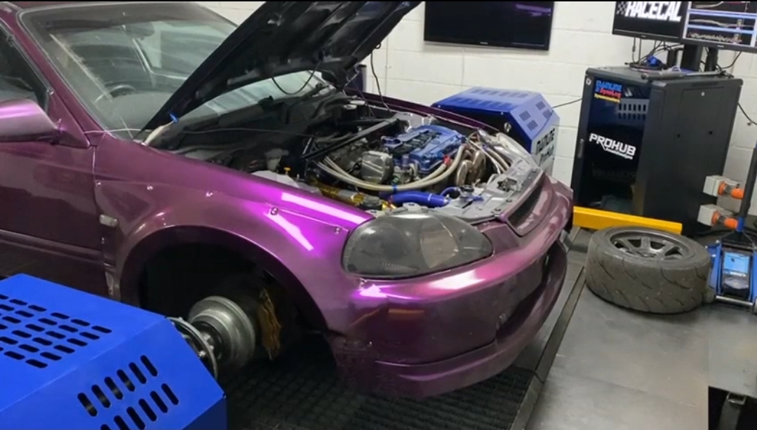
Use earlier layouts to spot where radiator, fan, intercooler and pipework choices affect hot-side airflow.
Hoses, hydraulics and wiring near the hot side
Wastegate reference hose, boost-control wiring, clutch hydraulics and brake lines all need the same process: route them away from the wastegate body, outlet pipe, manifold and downpipe; retain them securely; then check that fittings and bleed points remain accessible.
Do not let the sleeve hide damaged insulation, brittle hose, exposed copper or poor service access.
A/C, bonnet underside and intake heat soak
If you are keeping the A/C, check compressor clearance, hard lines, fan space and intercooler piping with the final manifold and downpipe fitted.
After real use, inspect the bonnet underside and intake-facing surfaces. Create separation first; then use a rigid barrier or reflective material only on a suitable surface facing radiant heat.
For a dedicated fault-finding process, use our wiring loom melting near the exhaust guide alongside the heat-management checks in this article.
Watch: Civic wiring-loom heat-sleeve test. This controlled test shows the sleeve’s role; it does not make direct exhaust contact or damaged wiring acceptable.
If the player is blocked, watch the Civic wiring-loom heat test on YouTube.
Honda B-Series turbo heat-management FAQs
Will a turbo blanket fit every EG, EK, or DC2 turbo build?
No. The turbine housing size, actuator, manifold, downpipe and surrounding clearance determine fitment. Measure the hot side and compare it with the current size guidance.
Should I wrap a B-Series turbo manifold?
Only if the manifold and route are suitable and it is causing a problem. Check its condition, joints, sensors, service points and nearby components first; do not wrap over a leak or damaged pipework.
How do I protect turbo oil and coolant lines?
Check the fittings and route first.
Once the line is supported and clear of hot exhaust parts through engine movement, measure its outside diameter and choose a suitable sleeve for the exposed section.
Do I need an external wastegate blanket?
It may be relevant where a correctly sized external wastegate sits close to vulnerable components.
Confirm its size and ensure the outlet pipe is routed safely; the blanket does not insulate the screamer pipe.
Can I use reflective tape on the manifold or turbo?
No. Use reflective material on an appropriate, clean panel, intake surface or other component facing radiant heat. It is not a replacement for exhaust wrap or a turbo blanket.
What should I check after the first heat cycle?
With the car fully cool, check for leaks, loose fasteners, blanket movement, wrap movement, contact marks, damaged insulation and any line or loom that has moved toward the hot side.
Build the heat plan around your actual B-Series layout
The best heat-management setup for an EG, EK or DC2 is not the one with the most products. It is the one that tackles the actual heat source, keeps vulnerable components safely routed, and is checked after heat cycling.
Start at the turbo and wastegate, then work outward to the manifold, downpipe, front brake-line route, hoses, wiring, radiator/fan area, bonnet underside and intake-side surfaces.
Once you have clear photos and measurements of the hot side, browse the product families that match the job rather than guessing from the chassis.
Shop Honda Turbo Heat Management PartsAbout the Author
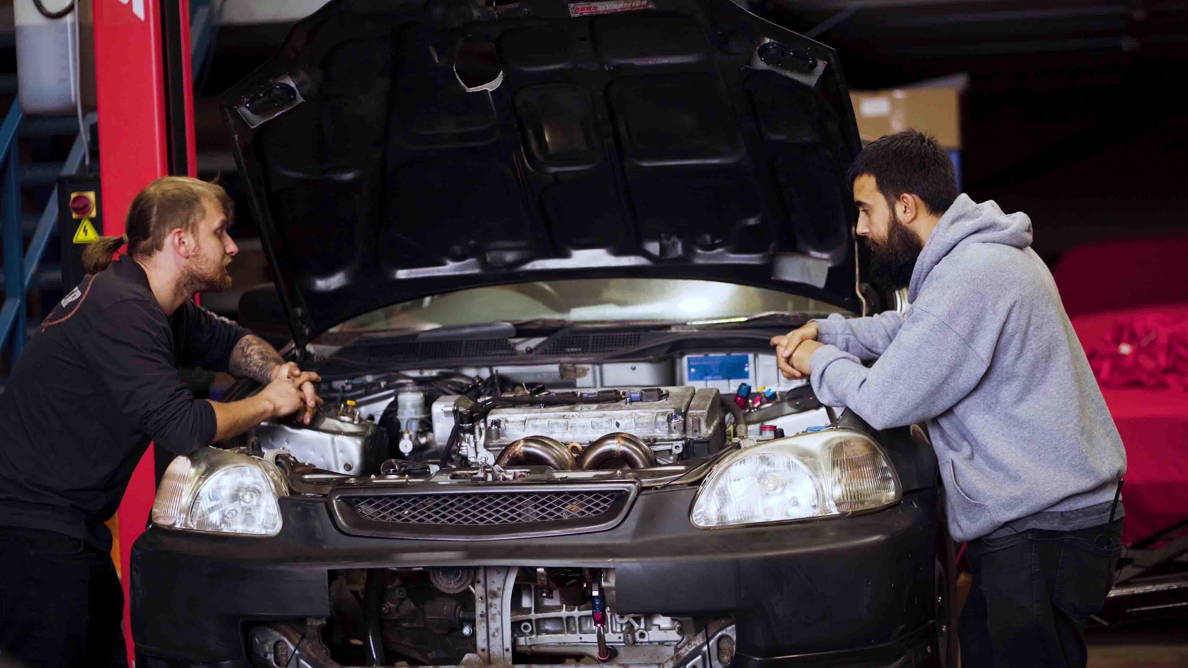
Exoracing is a UK-based performance-parts and heat-management specialist.
Since 2018, we have helped enthusiasts and workshops choose practical protection for turbo, exhaust, wiring, hose, line, and engine-bay applications, including our own Honda builds.